This build was constructed in 2016, as a race to finish before the film came out. Some corners were cut to meet that deadline. This blog post is based on the following build thread: https://www.gbfans.com/forum/viewtopic.php?t=40994
I was fortunate enough to find myself in California last week and was able to pick up a reboot motherboard from Joe. He got a new job immediately as he was about to ship, so he hasn’t had any free time while USPS is open to ship any of them. Very much worth the wait though.
Along with Joe, I met up with Paul Feig, who was gracious enough to sign my motherboard:

I made a custom aluminum shelf for above the faraday cage, cut up the small box for the two knurled knobs, etc:

Tried my hand at sculpting a few ugly fake welds and color matching them to the original metal:

And last night, I got started on the cover for the “nuclear love” box:


This week I’ve been mostly waiting for orders to arrive from various parts of the internet.
I did however make a little bit of progress on the Ashcroft gauge. I thought I’d offer up my thoughts on weathering it.
Here are the tools you’ll need:

-Window fog spray, rust-color primer, black spray paint (not pictured), acetone, an old beat up tooth brush, and Tamiya Color translucent yellow spray paint.
Step 1: Disassemble the gauge, and take off the clear face. Spray it evenly with a little bit of the window fog spray. Don’t do too much, as it isn’t affected much by the acetone later on.
Step 2: After that dries, cover it with some rusty red primer, nearly coating it. Make sure to dust in some black spray as well just to darken it up and make the rust/dirt not look so uniform.
Step 3: Dip an old tooth brush in acetone. Make sure the head is soaked, then start in the center of the gauge and with small circular motions, scrub the paint and fog away. Spiral outward until you’re happy with the amount of grime left on it. You may have to refill your tooth brush a few times.
Step 4: Once you’re happy with the amount of weathering left on it, dust the piece with the translucent yellow to make it look old and sun bleached.

Previously, I bent a piece of 1/8″ aluminum into the hose mounting bracket. Yesterday, I decided it was time to finish it.
I started by cutting a 1″ OD aluminum pipe down to size. Easy enough, but I needed a secure way to fashion both it and the ball valve to the bracket.

My solution was to take a 7/8″ OD pipe I had lying around, which fit snugly inside the 1″ pipe as well as snugly around the outside of the ball valve, and attach it to the plate, then attach everything else to it.
I did so by cutting it to size, then cutting out tabs which would be bent outward, holding itself to the bottom of the mounting bracket.
I meant to take pictures of that process, but got too wrapped up in the build.


After epoxying the two tubes and valve together, I then attached the remaining bit of 1″ OD pipe to the top of the ball valve.
After filling the top pipe and sculpting the big ugly welds on the base of the ball valve with plumbers epoxy, I was left with this:


It still wasn’t complete, though. Underneath the T&E connector, rests another plate of aluminum. Mine was made like so (Forgive my crude MS Paint rendering. I’m away from my beloved Photoshop at the moment):

After all that, this is how it looks:

I switched gears, and designed up some blueprints for the “V-Hook” which links the gun and pack when holstered.
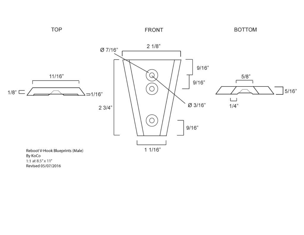
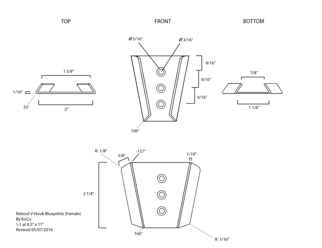
Someone who worked on the production said my V-Hooks looked spot on.
I made up a diagram and had the “nuclear love” decal made from cut vinyl.

Next, I decided it was time to finally start mounting all this stuff to the motherboard.
I needed to think ahead a little bit by making a mount for the green display at the bottom left of the synchroton, so I made the mount connect all of the boxes on the left side, including that display. I decided to do it this way to keep the same mounting bolts in the same places as the SDCC pack has.
Here you can see the basic design for the black plastic “spine” everything is mounted to.

Here are the boxes all mounted onto the mobo:


Then it was just a matter of slapping everything else on!

I’ve started working on the cage. I’ve been looking online for metal rings that would be the correct size, but I wasn’t able to find anything. One day I went into an ACE hardware to pick up some primer, and it hit me:
Tomato cages.
According to my measurements, the top ring should be 6.5″, the middle ones should be 9″, and the bottom one should be 9.5 – 9.75.
On the tomato cages, the smallest ring was 7″ OD, and the middle one was 9.5″.
So I picked up three and started cutting! I had to trim three of the four rings I needed to fit the correct diameter I needed, and wire-wrapped the overlap to secure them.
Each half of the hemisphere should be 2.25″ with a sum of 4.5″, so I cut additional wire from the cages to about 3.25″ and wrapped .5″ on each end around the corresponding ring.
You get all that?
Now let’s see some pictures!
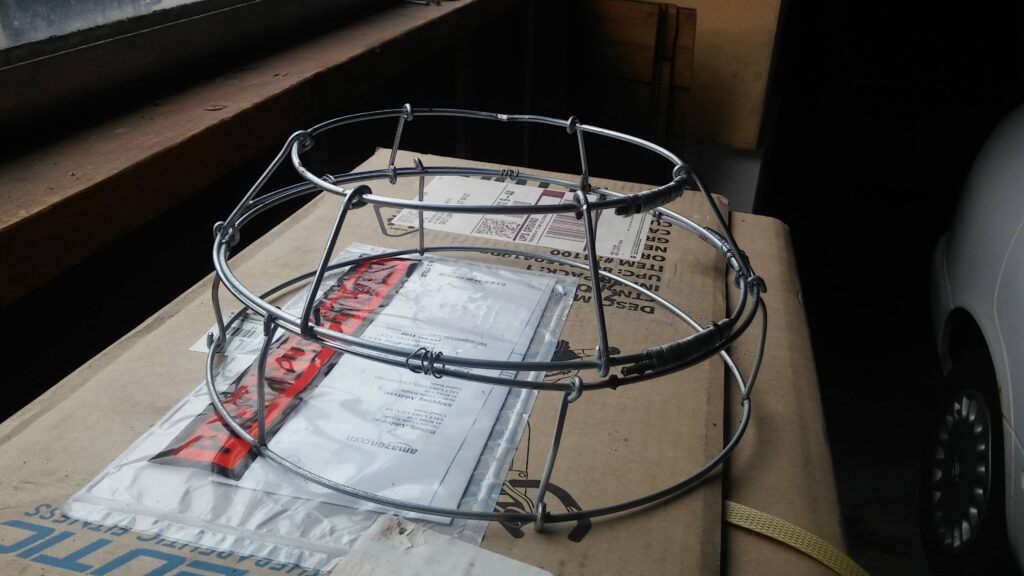
Each half is temporarily attached together via some wire. That will be fixed later.
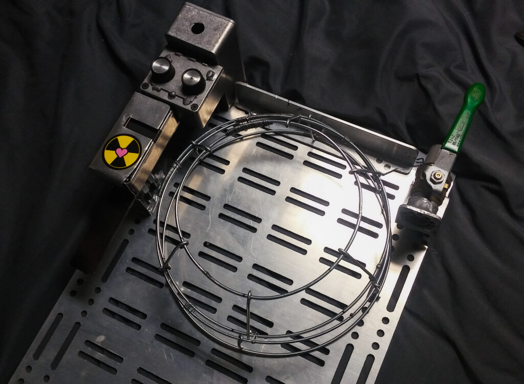
I’ve been very busy with work, though I did manage to make a small amount of progress in both rebuilding the cage frame and putting the mesh onto the cage.
My last cage was way too small. This one is still perhaps undersized, though it’s the closest I’ll get without rethinking how to mount the boxes on the left. As it stands, the rings on the cage are 6.5″, 9.5″, and 11″ respectively.

I decided to set out to make the frame for the cryo tank enclosure, so I made up some blueprints, bought some lumber and aluminum, and set off!
Here is a mock-up of the blueprints I made. I hope they help people!
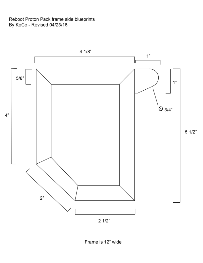
As you can see below, I made some hand-drawn blueprints so I could lay everything out and figure out the appropriate angles for the wood to be cut at. Then I said “screw it” and just sanded the wood to approximately the right angle.
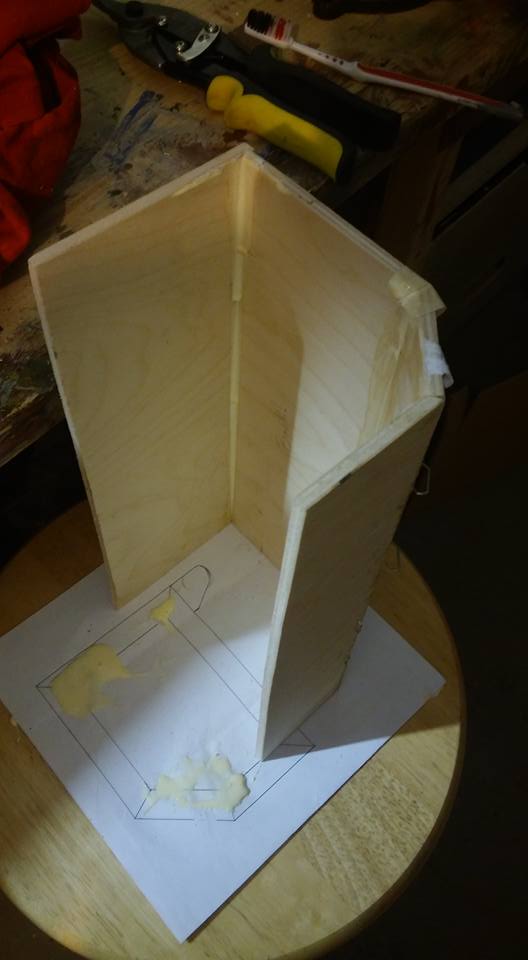
(I know, it’s not pretty. Just wait for it…)
The next day after the wood glue had dried, I got out the aluminum L-bar I had purchased (4 ft, if anyone is curious), and began cutting it into sections, then trimming one side to match the appropriate angles.
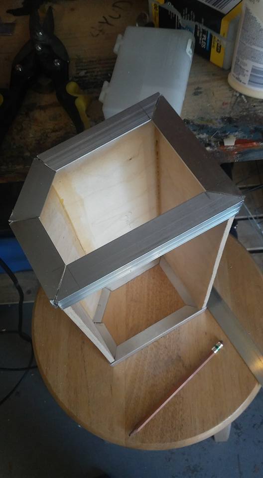
Now I’ll admit, I don’t know how to weld. It’s a terrible handicap to have in this hobby, but thanks to all sorts of adhesives, it hasn’t set me back much.
I secured the aluminum to the wood frame with some E-6000. It seems to be pretty stable.
After that, I decided to cut the front L-bar and drill holes into it to replicate what can be seen in the reference photos.
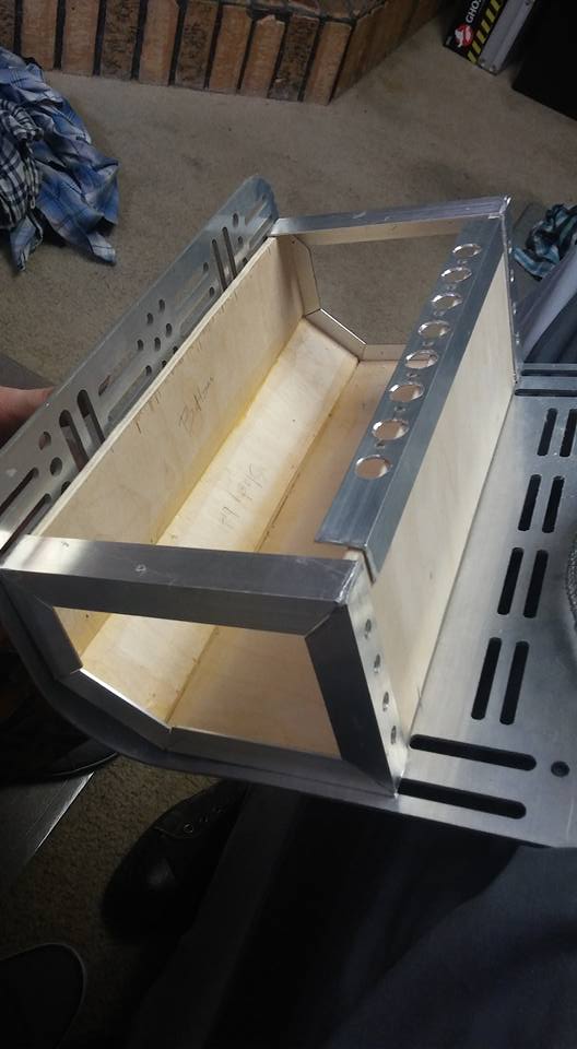
After a lot of deliberation, I decided the best way to create the “ears” that stick off the front of the box was to cut them out with long tabs on the backs that I could insert into the box and glue onto the existing frame. I didn’t take pictures of this process save for a picture of the square hole I made in the l-bar for the tab to be inserted through.
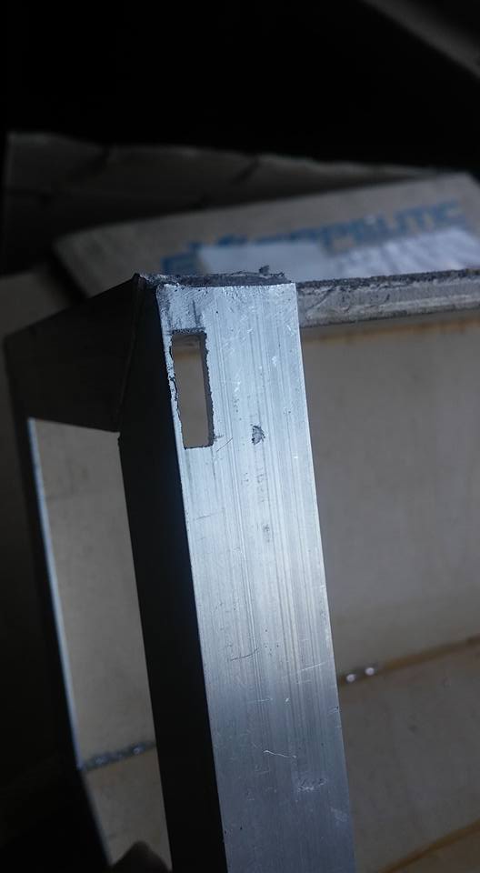
With the ears on I decided I hated the wood texture, and would never be able to make that wood look like aluminum, so I covered the entire top surface with thin sheet aluminum left over from the nuclear love box build. I attached the front bar on top of that as well.
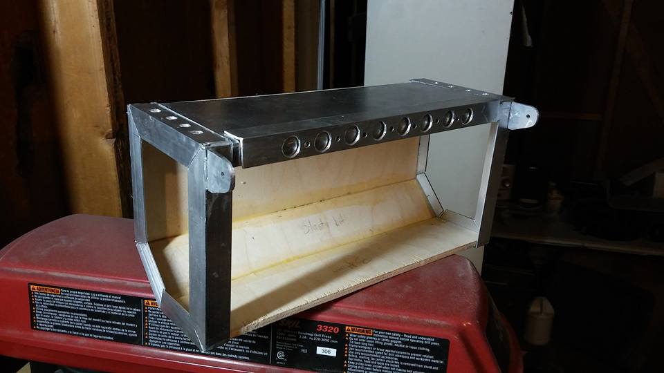
Then it was just a matter of attaching the side mesh, creating fake welds, and plasti-dipping the other exposed wood parts to protect it from the elements. (all that black will be hidden later)
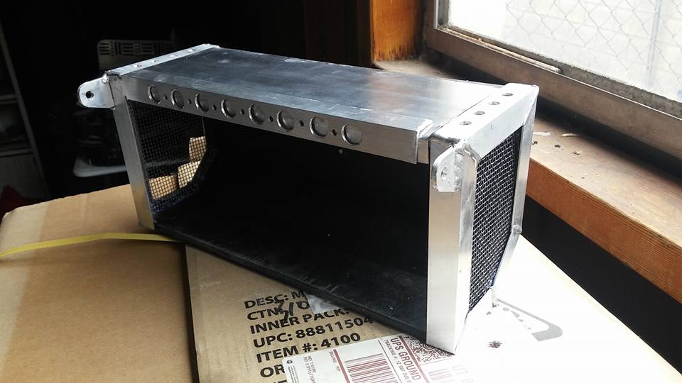
And here it sits now, waiting for its lid:
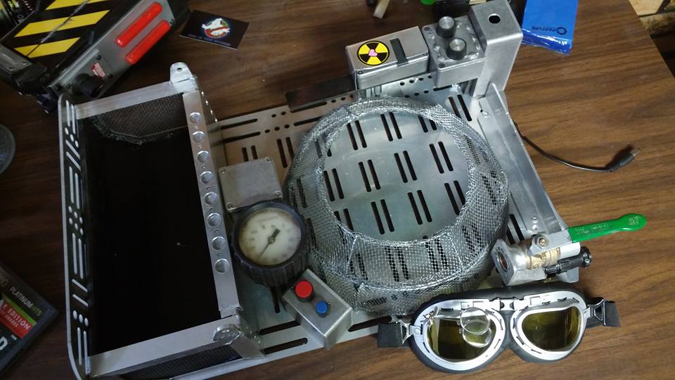
I decided to make a decal sheet of all the known decals needed for the various packs.
Now then, it’s been kind of a busy week. Doug released his STL files for his build, and Tommyb345 was kind enough to take on a commission to print a couple for me. There’s not a lot to talk about as far as the build process goes.
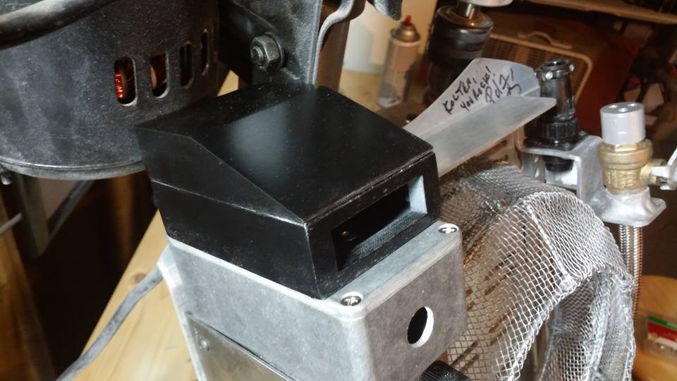
This upper display required little cleanup. Just a bit of sanding and it was ready to be painted.

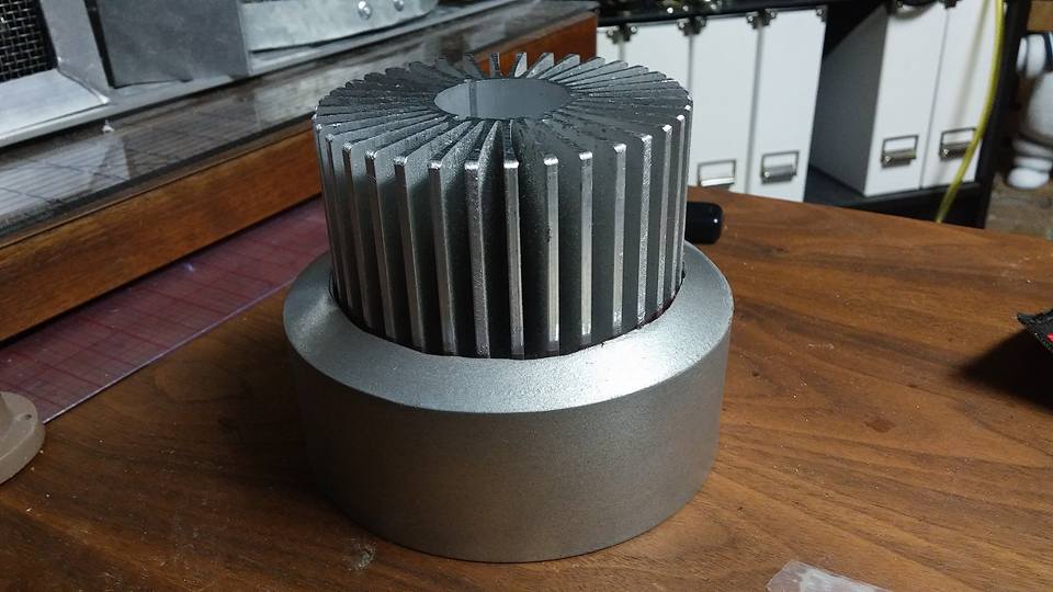
The heat sync required a lot of careful sanding. In the end, I couldn’t get it to look both clean and metallic…

I’m hoping to have this pack (without electronics) in about seven short weeks, just before the film is released.
This past week, I focused on the inside of the synchrotron.
I’ve seen a couple of production-made packs, and inside of one of them, I was able to just make out a shape similar to a large PVC reducer.
I’m not saying that is what it actually looks like inside the cage, that’s just what I remember seeing the vague shape of. I could be totally wrong.
Either way, that looks pretty boring, so why don’t we pick up a heat sync from eBay and spruce it up?
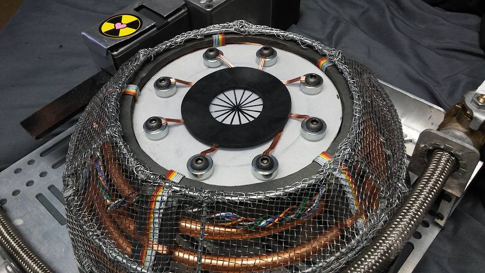
After the central tower was done, I decided to focus on the main structure of the synchrotron, something a friend and I call “the cereal bowl” for lack of a better term.
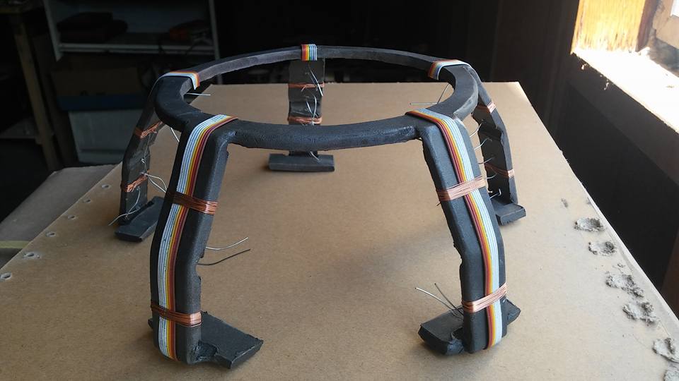
I started by cutting a massive sheet of quarter-inch styrene into a 6.5″ diameter circle with five legs evenly spaced.
I then heated and bent that into shape. Pretty easy stuff.
Thinking ahead, I drilled four sets of two holes on each leg just large enough to thread some wire through.
That wire will be used to hold the copper coil on the inside of the cage later.
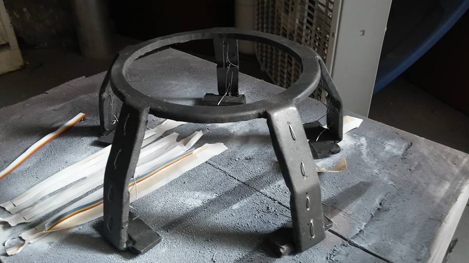
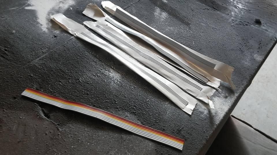
I then painted up some miscellaneous ribbon cable to somewhat match what we see on screen: an 8 cable ribbon with half of it being colored, half being white.
Once those were dry, I wire wrapped them to the cereal bowl. I wish I would have test fitted them first, as my copper wraps are admittedly perhaps a little low.
I also made a nice rope out of some wires and glued it on the inside of the cereal bowl. I tried to follow the colors from the SDCC pack.
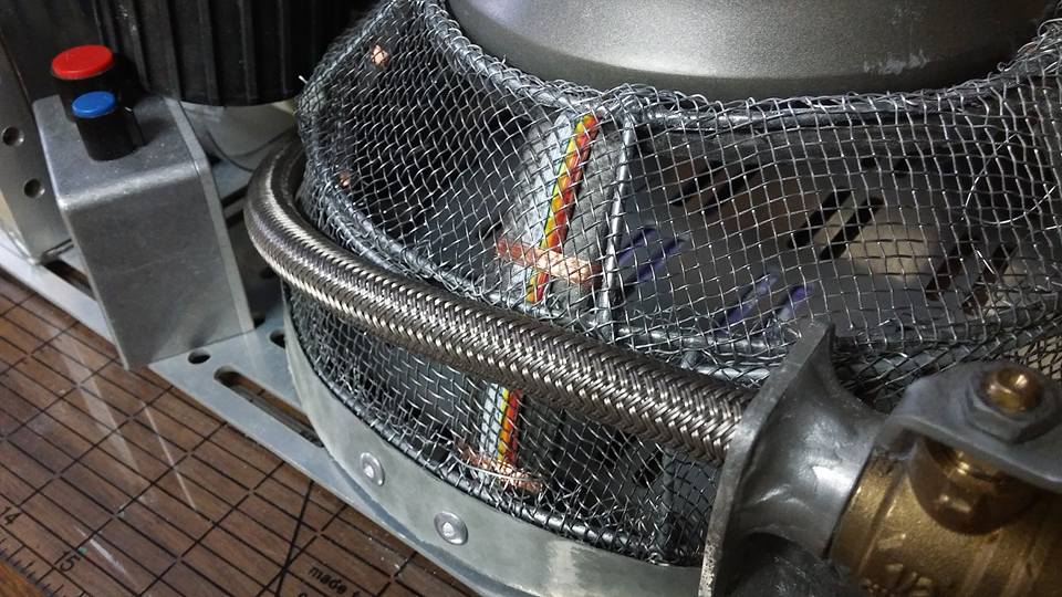
After that, it was on to the plate that sits under the cereal bowl. Once again, I took some mental notes while seeing a production pack in person. To me, it looks like acrylic painted from the underside.
I used clear styrene.
It was all fairly simple. I cut the styrene into shape, marked off the iris-like design in the center, etched that in with a Dremmel, then painted black over it, sanded the black down, leaving it in the etched area, added a gasket, some steel spacers, etc, and painted the underside white!
I didn’t take many pictures during all this, unfortunately.

After that, it was a simple matter of tying the copper coil inside with the wires I inserted earlier.
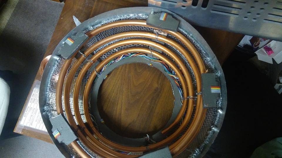
Here’s how it all looks together:

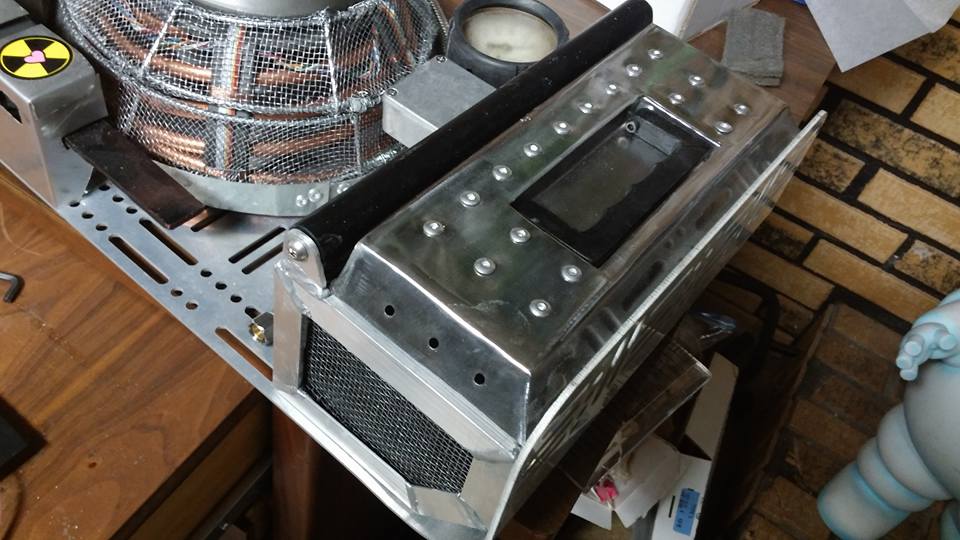
I really can’t thank “Ryan The Ghostbuster” enough. He built a steel lid for my cryo-tank box, and even did it to my exact specifications. It turned out beautifully to boot.
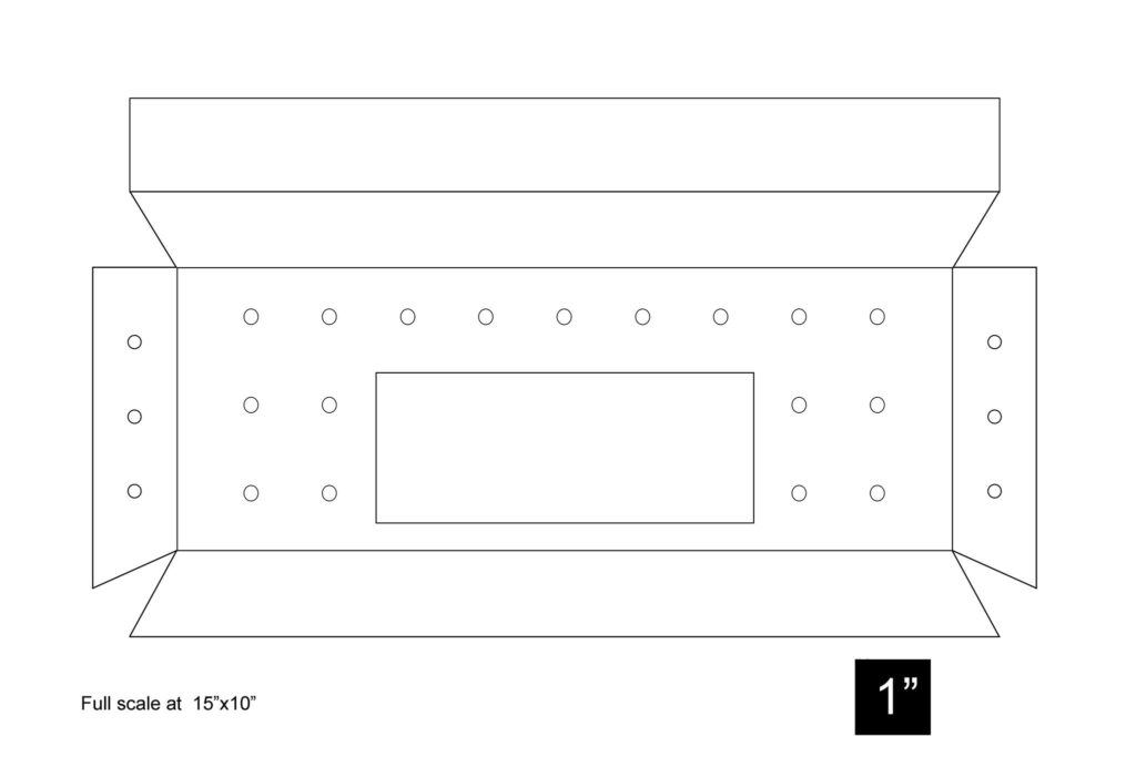
And here is a copy of my rough blueprints I made for him. These will work with the blueprints I posted previously for the sides of the cryo-box.
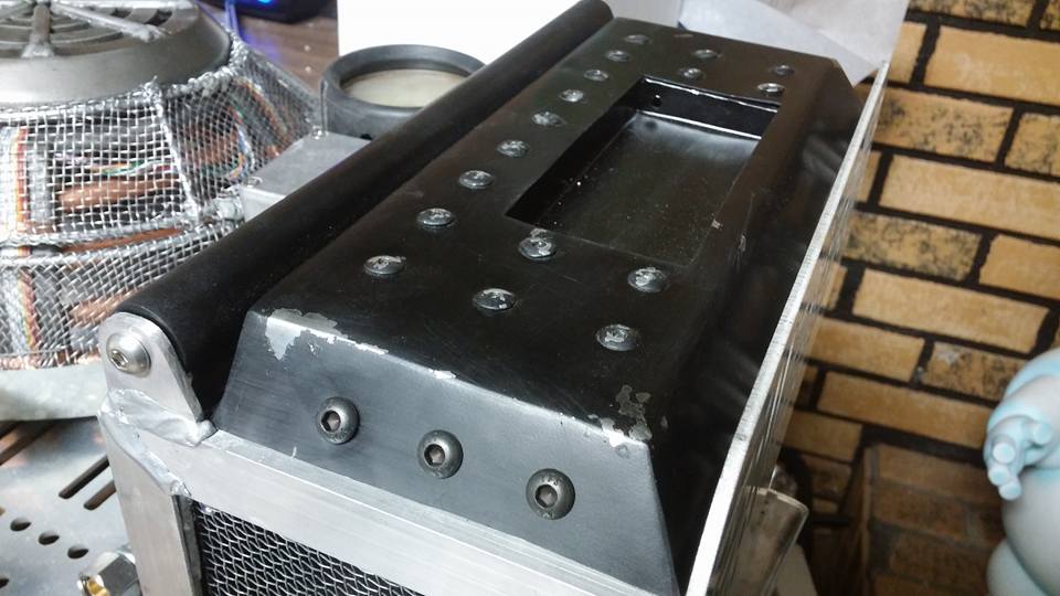
Here it is all finished up. I hated the idea of painting it all black and not being able to show off that it’s steel, so I used the mustard method of weathering and hit it with some steel wool to try to blend the weathering out a bit.
Once that was attached, I decided it was time to sort out the gauge I had before proceeding. The one I formerly had was 2.5″, which by my calculations is .5″ too large. Joe Luna and Parflagush (I don’t remember which of the two) found a source for a fairly accurate 2″ gauge, so we all got to work modifying the boot we had all purchased to fit the new gauge.

It’s not perfect, but it’ll work until we can find a good source for the 2″ boots.
Here’s how it all looks right now. I’m currently working on the V-hook mount as well as reworking the faraday cage to an accurate 12″ diameter.

Alright, so I, like many of you, was invited with my franchise to attend the L.A. premier of the new film.
So I guess that means I have no time to get this pack at least wearable!
Thanks to Tommyb345 for the 3D prints, partially based on Spongeface’s lower display design.
I decided I’d better work on fleshing out the rest of the big pieces missing. I started with Tommy’s prints of the lower display and RF circuit. Both were pretty straight forward. I did end up beefing up the cylindrical portion of the circuit, but other than that, it was just a matter of doing some finishing work.
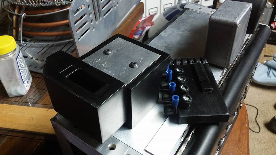
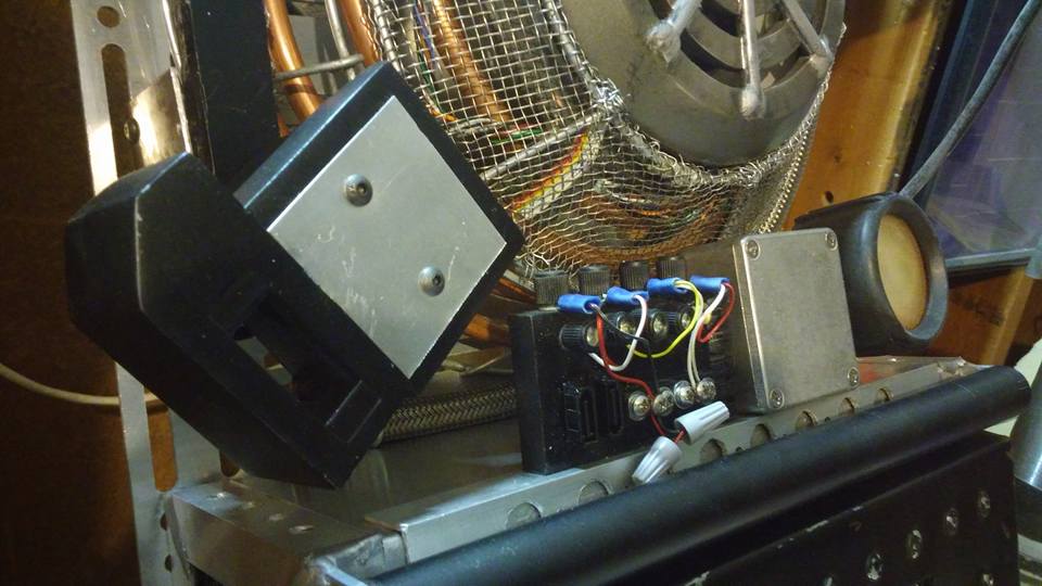
After that, it was on to the bumpers! These things are slightly tricky, but the geometry makes it really fun to build!
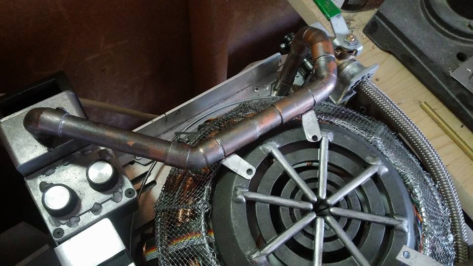
To make the mounting brackets for the heat sync, I bent the edges to conform to the 1/2″ pipe and riveted them together.
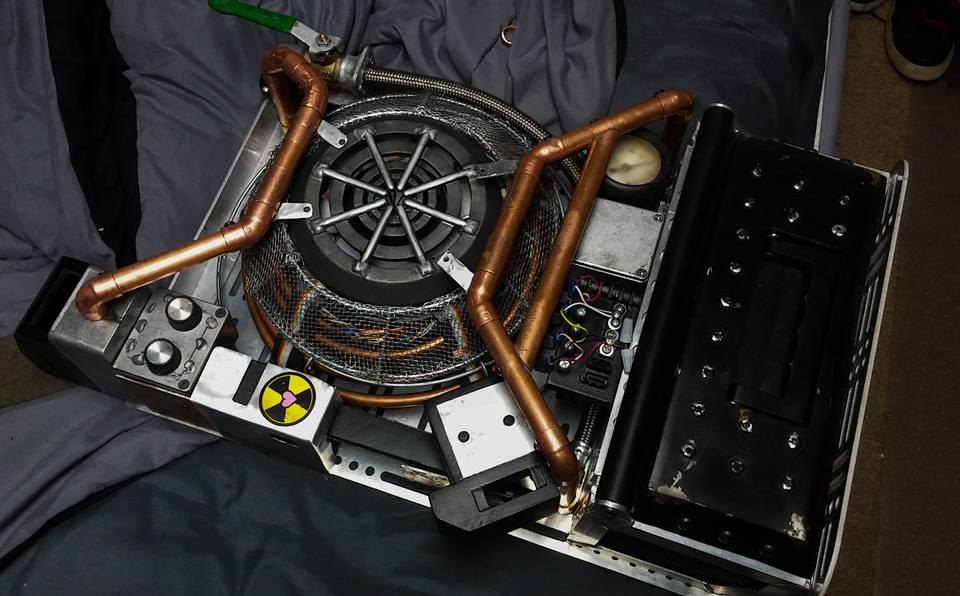
After that, it was time to paint! I did a few washes with gunmetal gray, black, and just a small amount of a more aluminum looking paint. I think it looks similar enough to the SDCC pack, though I may revisit it at some point in the future.
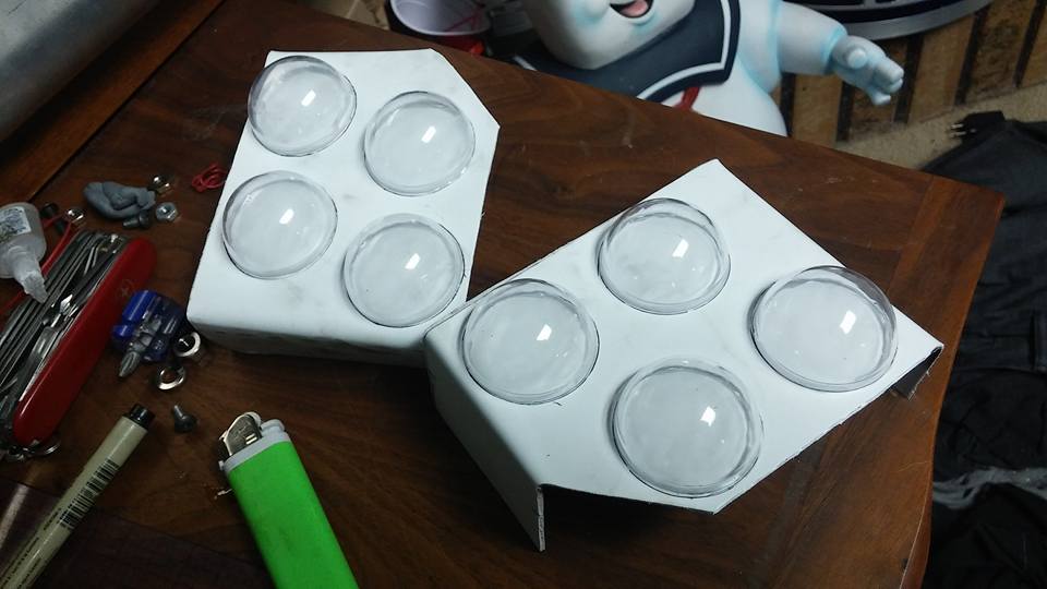
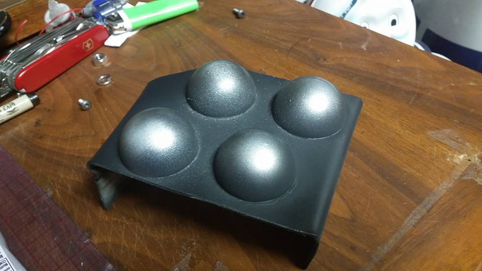
Next up, I needed to make the facades for the inside of the cryo-box. I cut and bent styrene to the correct shape, then glued some 3/4″ acrylic hemispheres to them. I made a template so they would be exact in their alignment.
A simple flat black paint job with some “metallic” highlights brought us to this:
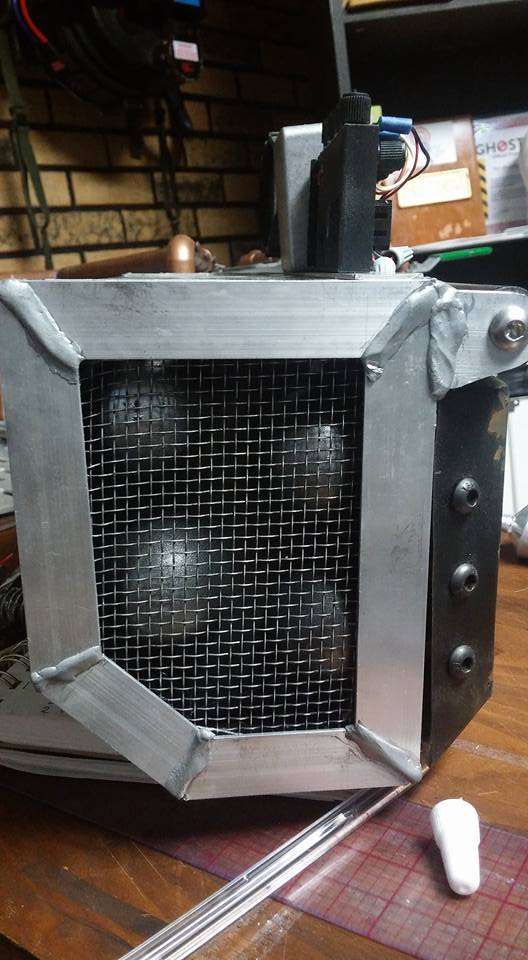
Finally, I got some more mesh in to rebuild the lower half of the faraday cage for the upteenth time. This time it should be exact.
For the metal band along the edge of the faraday cage, I decided I didn’t want just a flat band going around the outside. I wanted something with a gradual angle to it, as the screen used packs have.
I was fortunate enough to have a tape measure with me at Walmart, and found this bucket. Measuring it out, it had the exact slope I needed. I cut the band out, painted it a gold color with a fair amount of the bare metal showing through, and it looks pretty close to the real one to me!
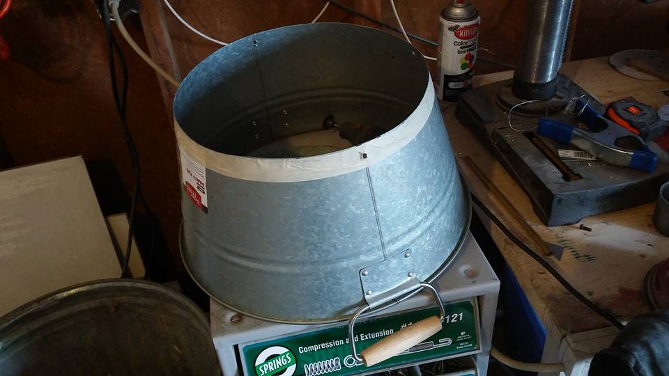
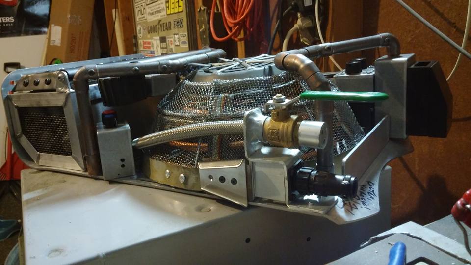
Now most everything is ready to mount now minus the electronics and gun.
Oh, I guess there are the straps, too…
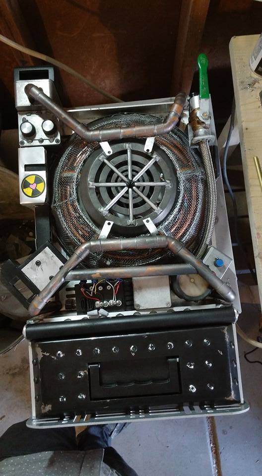
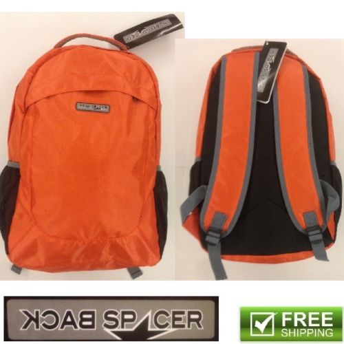
For the straps, I ended up sourcing a backpack to very heavily modify. Only the base shoulder straps really remained. I should have just started from scratch.
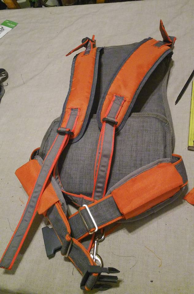
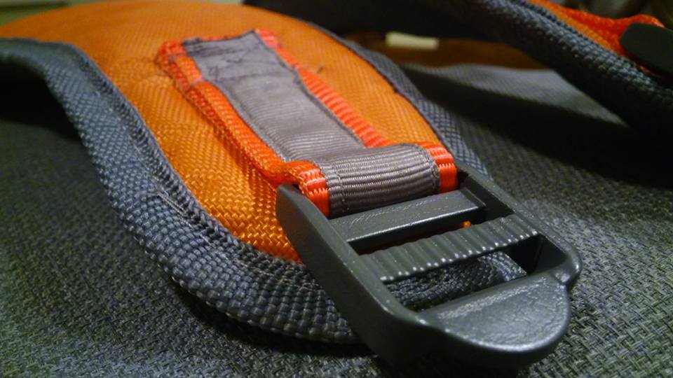
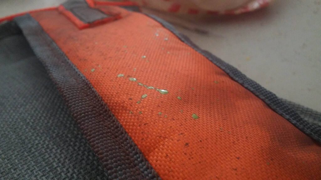
So I was able to get the pack mounted and wearable by July 7th as I was hoping.
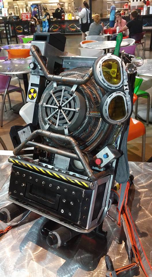
Because I pushed really hard on that final week, I was able to get it done and wear it in L.A. to the world premiere. That was pretty awesome.
I was able to get Kate McKinnon’s and Kristen Wiig’s signatures with the worst Sharpie in the world:
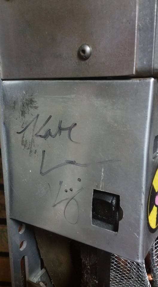

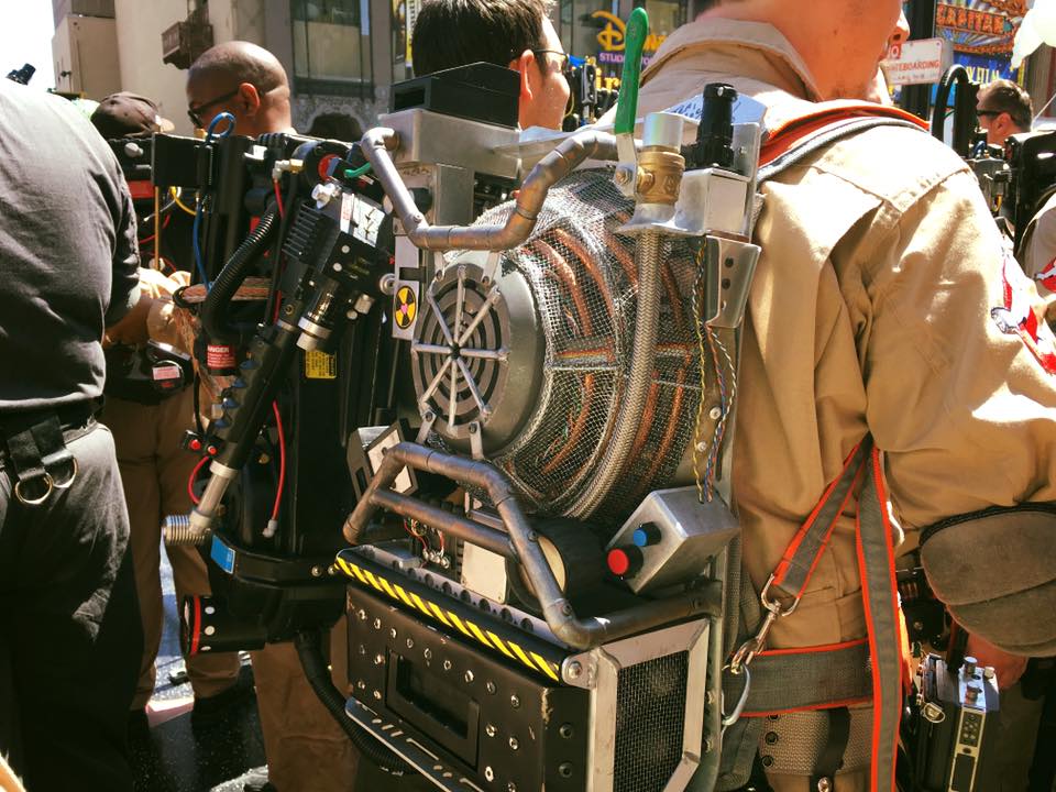
The trip to the premier was an insanely fun time. This pack ended up being worn by the MC on the red carpet, afterwards, my friends and I got to attend the very screening that the cast was at.
