This blog post was adapted from a build thread on gbfans.com covering an ongoing build from 2013 to 2019. It was started when I was 18 with limited tools and knowlege.
The full build thread can be found here: https://www.gbfans.com/forum/viewtopic.php?t=40204
My build began in February of 2013 with a Multimedia Mayhem gun kit. This gun will be scrapped later in the build.
I didn’t have ANY knowledge on the gun’s construction at the time, so I suppose that even though it’s not terribly accurate, it came out better than it probably should have. That’s the main thing I want to replace one day.
Here’s a picture of all the pieces before assembly:

The parts are as follows:
-Aluminum MMM gun kit
-MMM U-handle
-Nick-a-tron “thrower boxes”
-Jack Doud’s pneumatic elbow/tubing/straight

I later upgraded the nozzle of my “gun” with sheet styrene. I traced the reference photos hosted illegally on Cyland’s website to ensure it was completely accurate.

And added some accurate Parker fittings:

Now some notes on the “gun”:
-Make sure you diagram things before assembly. Make sure you know where things are supposed to go instead of assuming what is accurate.
-MMM’s gun kit in inaccurate in almost every way. The nozzle isn’t long enough, the back “end cap” covers the piano hinge, the ring on the back end cap is supposed to be offset, aligned with one edge, both the nozzle and end cap should have four holes for screws instead of three, the U-handle hole should be mounted nearly on the side of the “gun”, not centered on top, and the hole for the ball valve handle should be on the seam, not below it.
Now onto the pack, itself!
I purchased the ALICE frame and some scrap aluminum first. Here is my humble attempt at the frame:

Now with some more of MMM’s fine aluminum on it:

For the “pump boxes”/electrical power supplies, I decided to create a custom stamp online with the template created by the talented Goffcorp here: http://www.gbfans.com/community/viewtop … 89#p473789
After that, some inaccurate heat sinks! (cutting those out with a hacksaw is murder):

My original acrylic red ball and its aluminum replacement , also, the hose is the type that is used on a manual water syphon pump. Aesthetically, it looks very similar to the screen-used one.


Then I got a very big package in the mail. The gracious vbvabuster told me where he bought the bollard covers he used as his main tank. Needless to say, I went the same route. It’s really the best way to construct that tank in my opinion. I used two bollards joined in the middle with a ring on the inside and Gorilla Glue. Gorilla Glue is polyurethane, which means it binds the polyurethane bollard covers extremely well.

I attached Nick-a-Tron’s “lower tray” and a generic heat sink found on ebay went on next. I made sure to include that weird piece of aluminum that sits there with the tape on it. It’s all in the details.

I finally got the main tank done and went on to the hoses from the pack to the “gun”.
The outer hose was made of a car bellows. If you go to ebay and search “moulded rubber bellows”, you should be able to find some similar, though they no longer carry the size I bought. I purchased the last two and had to settle on the final hose.


Moving right along, the 5″ tank was made of a bollard cover with an acrylic dome on one end. You’ll notice I used a set of Kingsword lights. They’re the first things I bought for the blower. I couldn’t betray them by using accurate lights, though I may end up upgrading to Cateyes later.


The 4″ tank was made from an acrylic tube and two acrylic domes. It cracked when I mounted it. Turns out acrylic is prone to doing that unless you’re careful. THE MORE YOU KNOW!
Here’s a shot of the two boxes on the side tanks:

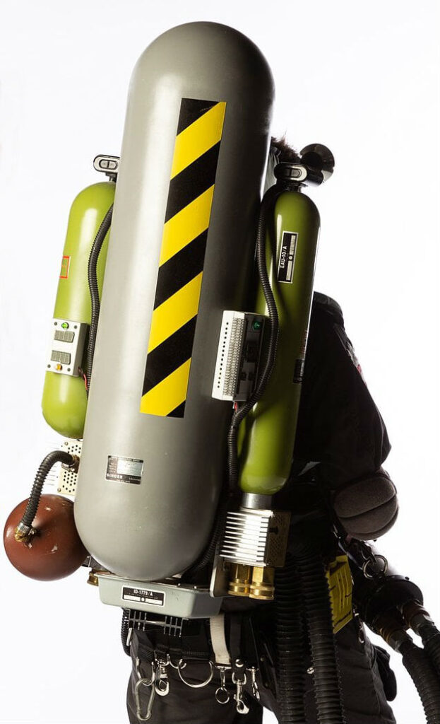
And here it is all mounted together. I used Nick’s method of mounting. I got a compass and drew three circles the same diameter as the tanks, then measured the distance between them and drilled away!
Decals by FunkPunkTwang, lights by Crix:


Notes on the pack:
-Don’t ever guess when it comes to mounting everything. Ever. My frame crossbar is crooked, as is my lower tray. Don’t do it.
-Drill into acrylic slowly. Take your time.
-You’ll want an aluminum red ball. My acrylic one cracked almost immediately. They take quite a beating.
-The Alice straps have an O-ring riveted on the end. That’s a detail that most people somehow seem to miss.
-The reversed LC-1 straps don’t go through the little loops on the frame. just loop them over the top of the ALICE frame.
-Bollard covers are a great base.
Now onto the “soft” elements of the pack:
There’s not a ton to say on the subject of the kidney pad and head rest. I’ll just show pictures:


The last thing I did on the pack was create a vest. I started off with a Winnwell hockey vest. After several dyeing attempts, I decided it best to re-cover the pads with the same fabric as I constructed the head pad with. The pads I used aren’t 100% accurate, but after a year of searching, it was the closest thing I could find. The most notable differences are the break in back and the flatness of the front. The accurate pads should flare out at the bottom of the front.
I used the same method as gEkX to make the front plates.


Thanks to an image I received from a friend, I was also able to see part of the back of the blower’s vest. Here’s a picture showing what I replicated based on what I was able to see:

Four metal plates. Two on the shoulders, one on the mid back, and one on the lower back. I don’t have clear enough pictures to try to replicate the lowest one. I can just verify it exists. The bottom of the mid-back one was all guess-work, too.So I’ve held off making this thread, as I wanted some “beauty photos” to show off first.So naturally I bought a Gibson and Barnes suit, BlkMesaHero belt, made a reasonably accurate GB II belt gizmo, and waited for a con.

Here’s the finished product:


Well, I decided to scrap my blower’s gun and rebuild it more accurately, based on ThrowingChicken’s measurements.
I started with the U-handle.
Here’s a picture of the original:
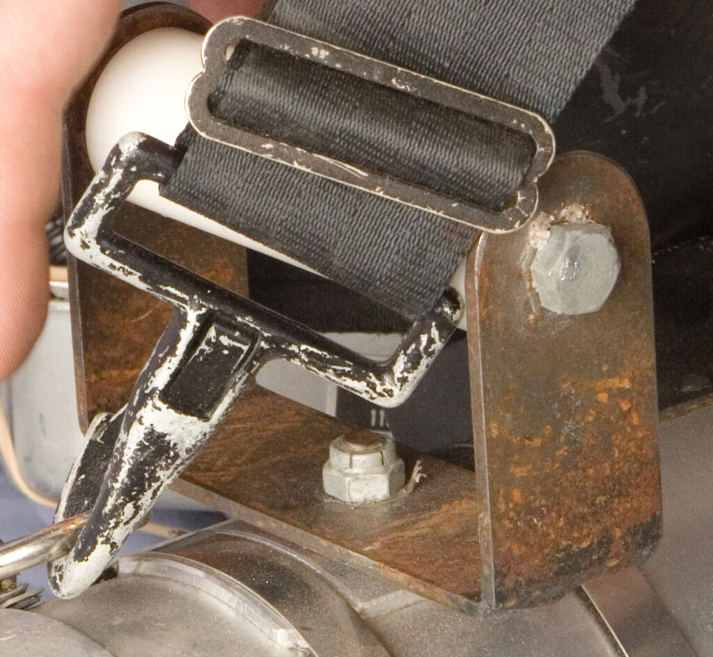
Here are the changes I had to make to the Multimedia Mayhem one:
1. Round out the corners on the U’s sides.
2. Make a new mounting plate beneath it. This must be duel-leveled as shown in the picture, where it steps up just behind the hose clamp.
3. Cut the sides off the bottom of the “U”, and weld them on, as opposed to just having a bend. (This will likely be done in the future)
Here is a picture of mine, as it stands now:

I cut the mounting plate out of my old gun’s body to ensure it is round and about the correct diameter. A new body is arriving shortly, which will be thicker and much more accurate.
I also painted up the old strap hardware:

After much searching, I ID’d the correct green lights used on both the slime blower gun as well as the larger project box which sits to the right of the main tank.

They’re Arcolectric LHM628G panel mount lamps.
After a little wait between updates, here are all of the nifty parts I’ve been gathering:
Accurate strap clips:

Accurate 5/16″ Legris straights for the red hose and a “milky” neoprene hose that will be painted red!:

An aluminum cone with the correct angle as the screen used nose cone (pictured with MMM’s steel nose cone):


And to top that all off, I even received and installed the accurate elbow and reducer on my red ball finally.

I published the “pump box” and heat sink blue prints for others’ use.
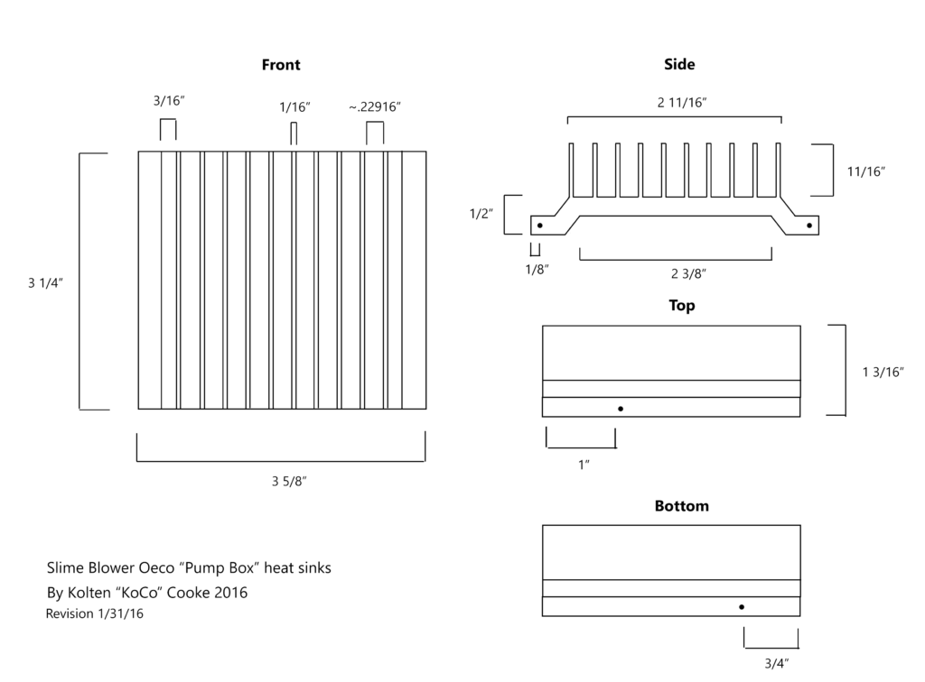
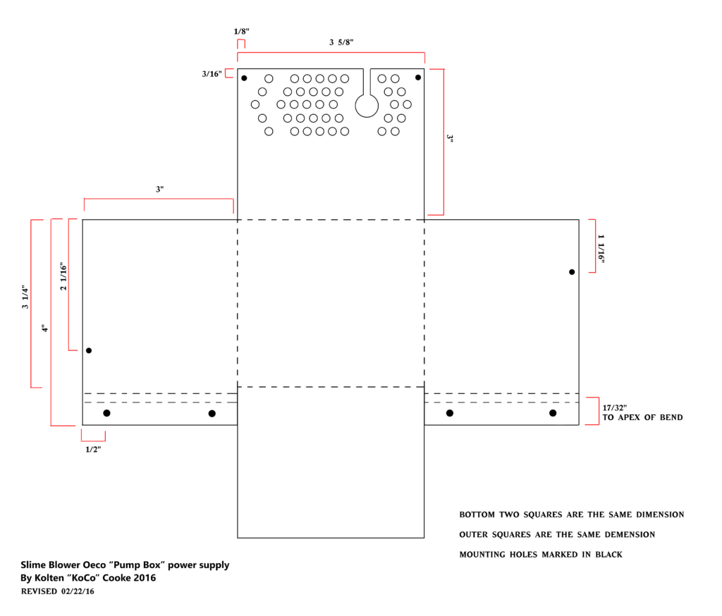
These parts were made by Heavy Props (Crix).

Well, finally some progress has been made! I’m gonna try to get this gun done as soon as possible so I can start refurbishing the slime blower, itself.
First, I cut down the 4.5″ pipe on the bandsaw. The two caps fit nicely after some grinding.

Then I decided it was time to paint the back end cap and get the matte finish I wanted on the nose cone.
I painted the end cap with some black semi gloss paint, masking off areas I wanted chipped. I was going for a worn look so I hit it with some steel wool afterward.
The nose cone, I polished with a brillo pad and some lubricant.


Next up, I drilled out all the holes on the sides of the slime blower gun. I haven’t had the chance to pick up the hardware for them yet. That’ll have to wait until the next update.


I then decided it was time to face my greatest fear: cutting the trench for the ball valve handle. I also wanted to see how those little green lights looked on the gun, so I drilled that hole as well.


That little “ON ->” sign is present on at least one of the screen used guns, to remind the actors and prop master which way to turn the valve to activate the spray.
I’ve been preparing to build the internals for this project. It’s gonna be a heavy beast, but it’ll mostly be for display, so oh well.
I went ahead and started on the nozzle. I ordered two small steel tubes, one slightly shorter and thinner than the other. I heated the large one, and was able to expand it just enough to hammer the smaller one inside. Once cooled, the two became inseparable. I wanted to go with steel, as I want to eventually replicate the rusty look of this tube.

I then took a 1.5″ disc of aluminum, and drilled all the holes needed. I created the notches with a dremmel sanding drum. This was done sort of haphazardly, as none of the notches on the real deal are symetrical or evenly spaced. Finally, I tapered the whole thing toward the back with my disc sander.

Here’s the evolution of my blower nozzles over the years. The left is an old MMM one, the middle is a styrene one I made, and the far right is the latest and greatest.

I couldn’t find a flanged castle nut that looked right to go on the end, so I made a “close enough” one out of a metal skirt and a normal castle nut, which I ground down a bit.

And here it is assembled and test fitted into the front of the gun!

A couple years ago, I was able to get some good reference photos of the gun handle. Unfortunately, I’m not able to share those images with the community. I am able to show everyone my findings in the form of blueprints and replicated parts, however. One of the main pieces I got reference of is the ball valve handle.
There is one photo I was able to find in the public showing the handle. Here it is:

From this image, you should be able to verify that the general shape of my build is correct. It’s hard to extrapolate much more than that from the above image, but it gives you a grounds to trust that what I’m saying is relatively accurate.
Here are my plans for the KoCo Slime Blower Ball Valve Handle:
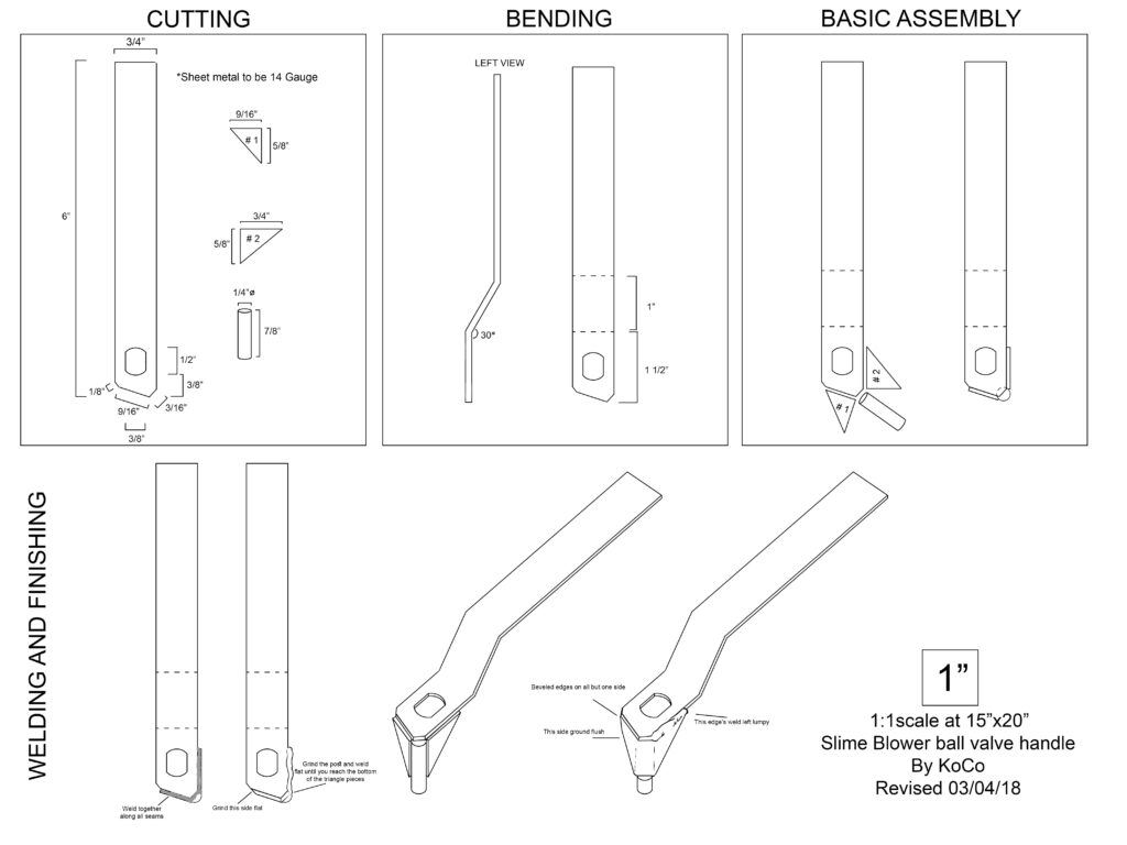
The next part is derived from the wonderful plans that ThrowingChicken sells. His plans are what my build is based on. He did an amazing job with the limited reference he had. One thing that was not quite right however was the trench that the ball valve handle swivels through on the side of the gun. With his permission, I altered his blueprints and am able to share this information with everyone. (Thank you!)
I started off by cutting the appropriate parts from a 14 gauge sheet of A36 mild steel. Not a lot to say here other than a file is your best friend when cutting that hole in the middle.
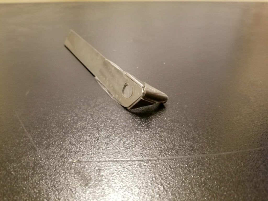
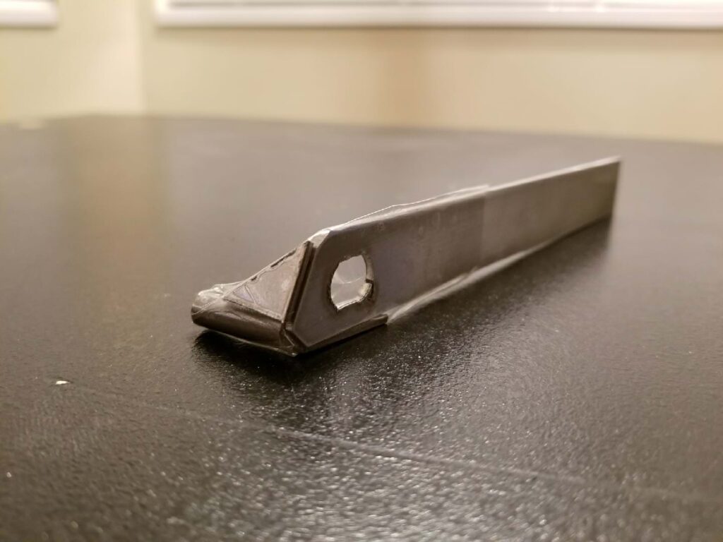
I then bent it into shape with the ol’ vice (not liquor, the metal one).
After that, I sent it off to get welded by a family member. Post welding, it’s not perfect, but it’s looking pretty good! There’s some hard grinds on there, so we gotta smooth that out. There’s also some bevels that need to be done.
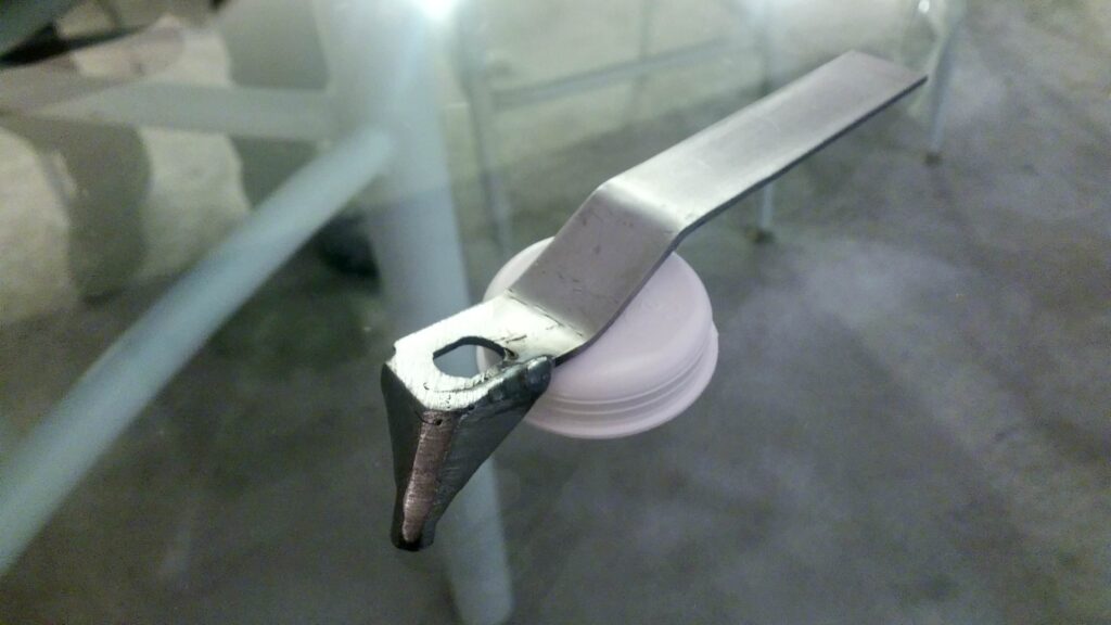
Here it is cleaned up a little bit. I could have gone further with it, but that’s alright. I wanted to take photos to post. I’ll do more on it later. I also cut a 3/4″ dowel in half, painted the end red, and stuffed it into the classic AME bike grip. In the first photo in this post, you can kind of see that the handle is mounted like this on the original prop.
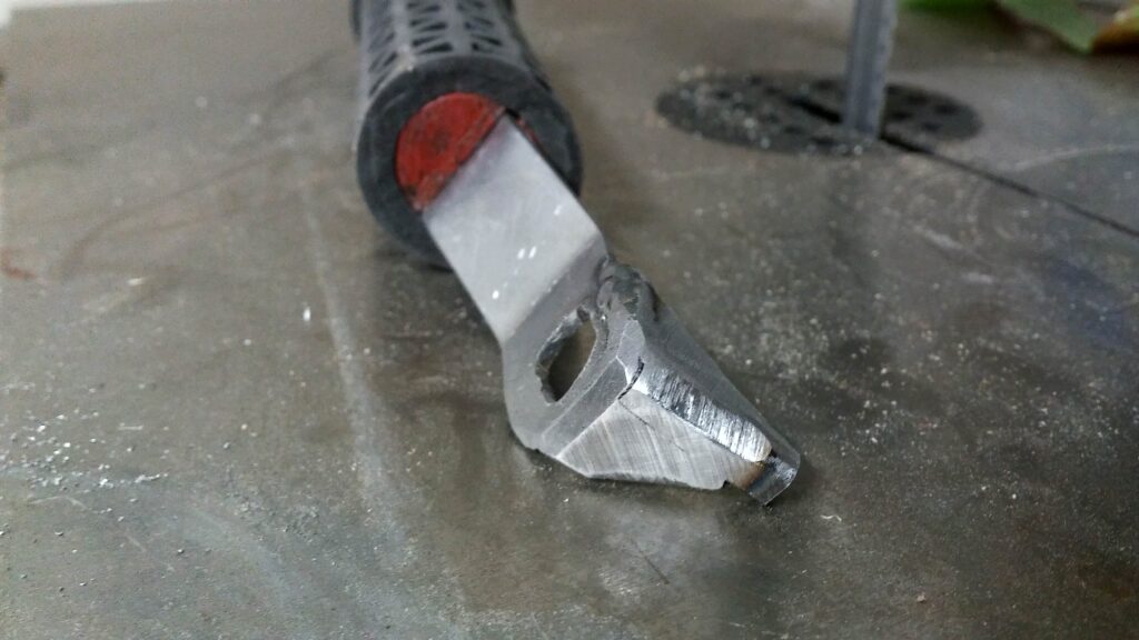
I mounted the ball valve in the gun body temporarily with some wire so I could take some shots and help line up the handle and reshape where necessary.
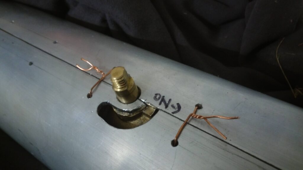
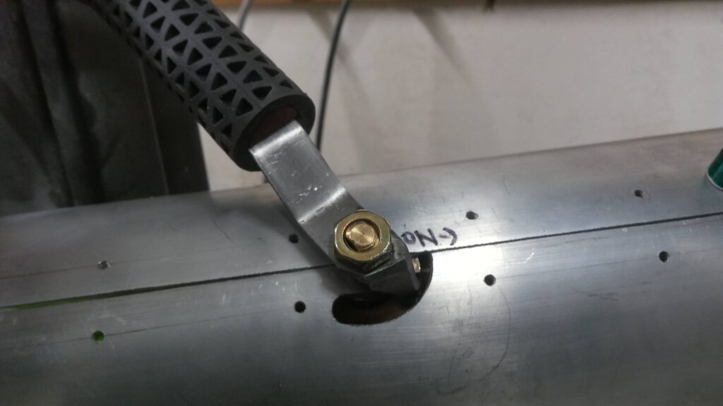
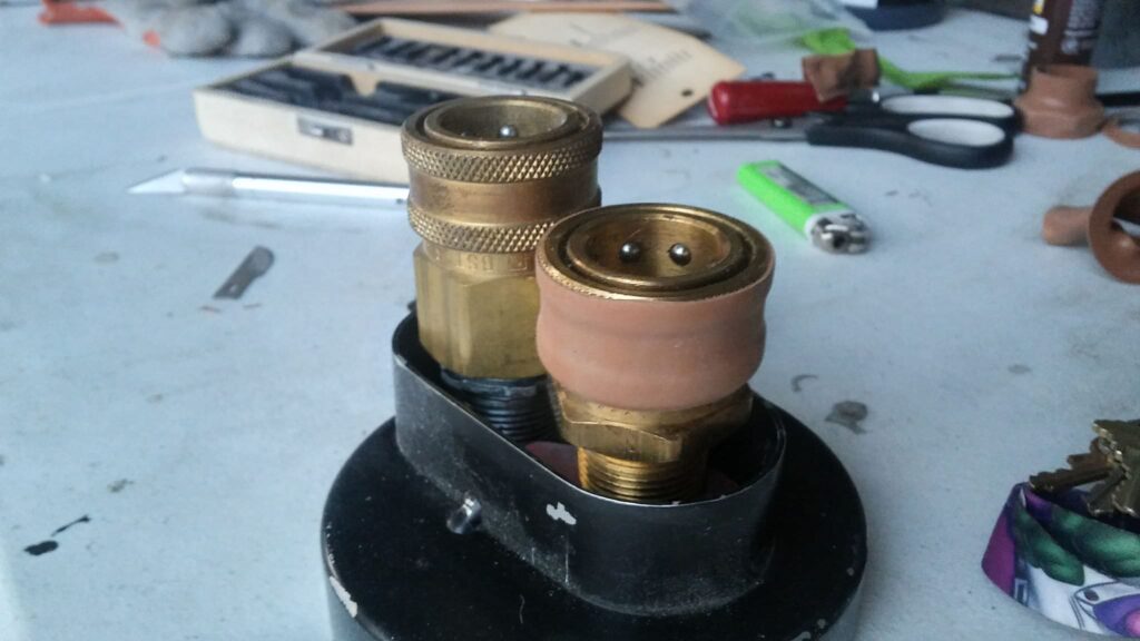
I’ve been trying to find either heat shrink tubing or gaffer tape that was a light brown to go on the end of the smaller Parker fitting on the back of the gun for quite a while. I finally was able to find some heat shrink tubing at a local electronic store that was the right size and just about the right shade of brown.

This past week I worked a lot on the blower’s internals. I originally wanted to make them out of steel conduit/fittings, but that ended up not working due to the small space available within the blower. So I went with PVC. If a fitting ended up being too large to fit inside the body, I could just cut it down and cement it in place.
First I jotted down a rough diagram with all the measurements I needed on it in full scale. I took that to the hardware store and tried laying out all the 3/4″ PVC fittings I would need, keeping in mind that some of them would be trimmed.
I then assembled it all, and began cementing everything in place.
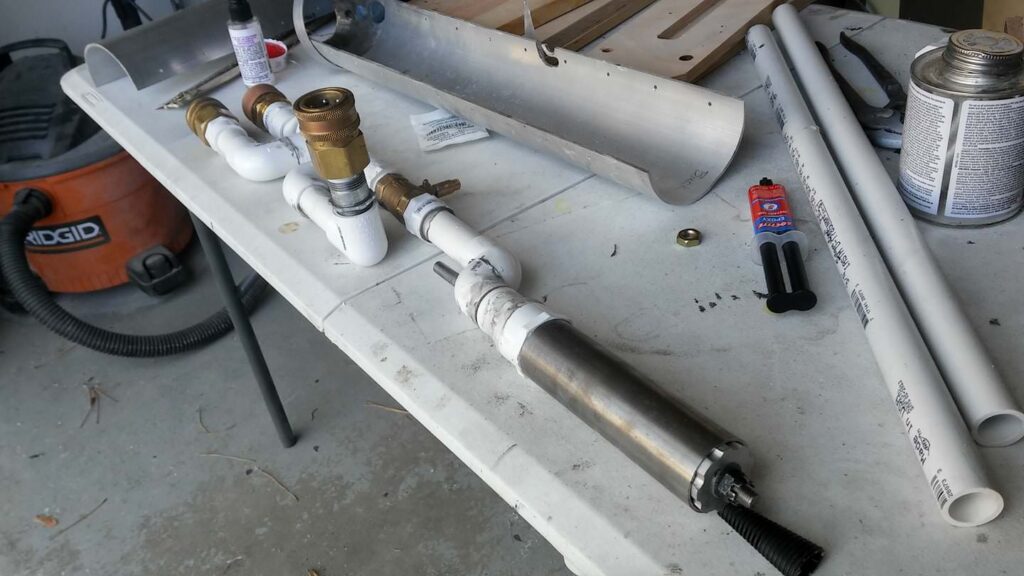
As you can see, the nozzle is held on with some all-thread, which goes through a PVC elbow out the rear. Additionally, just below the large brass fitting is a conduit nut, which will support most of the weight, keeping everything balanced, and not putting excess pressure on the PVC.
After that, I got some 4 1/4″ acrylic discs which I made into supports for the pipes. The steel nozzle is pretty heavy, and it was putting a lot of stress on the cobbled together elbow behind it. I made sure to make room for the threaded rod from the nozzle to pas through as well.

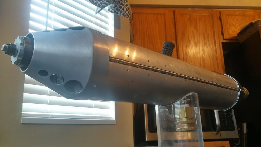
A week ago or so I drilled and tapped 44 holes on the blower! Yay!
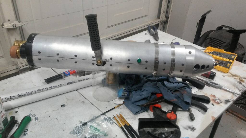
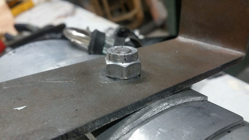
I then added the U-handle with the lock nut I sourced about a year ago. Lookin’ nice.
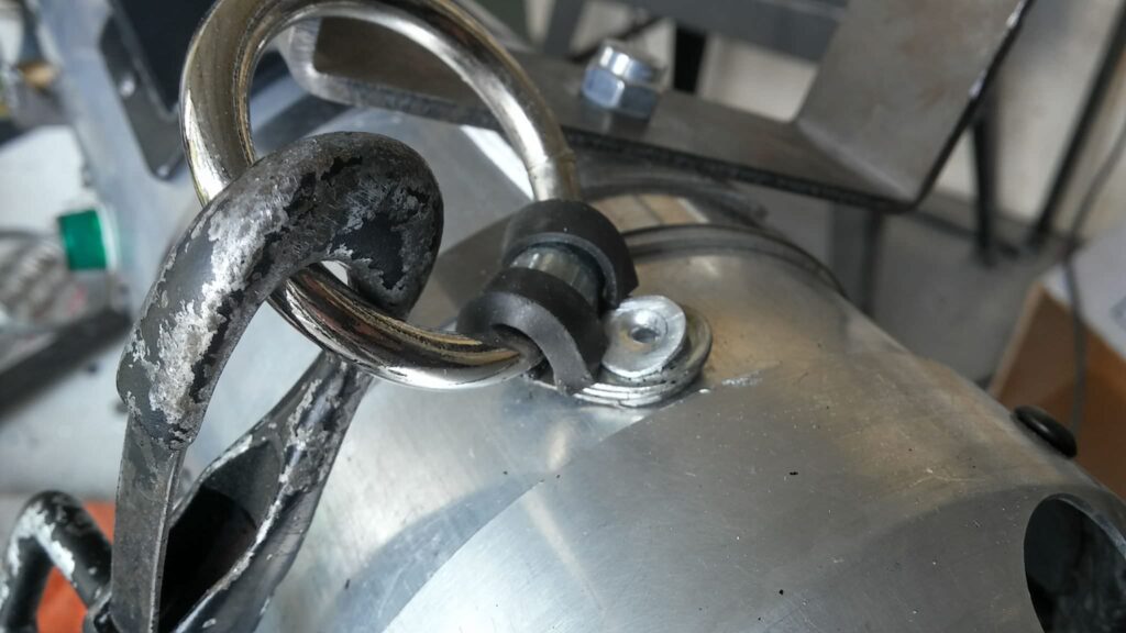
The biggest thing I wanted to cover in this post was the strap. In the film, the straps are attached with rivets. Very thin and oddly sized rivets. They are so thin that the strap being pulled up over time caused them to bend and become concave. I took some large rivets, ground them to size, then flattened them until they would deform in the way I wanted. After prying up the edges a bit, we’re left with this:
That’s basically it. I just need to install the three static LEDs. Here are some shots of the (nearly) finished product!
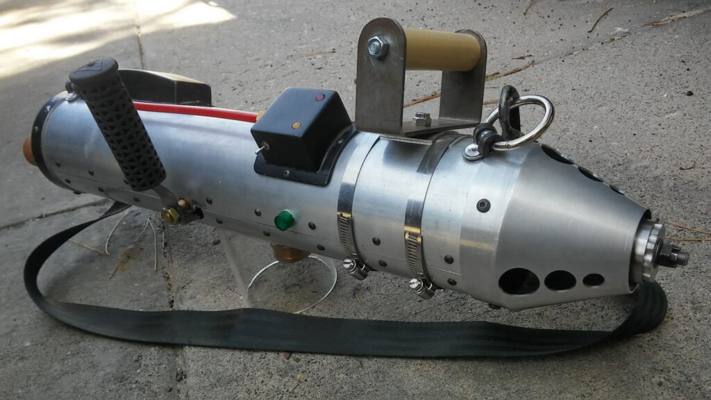
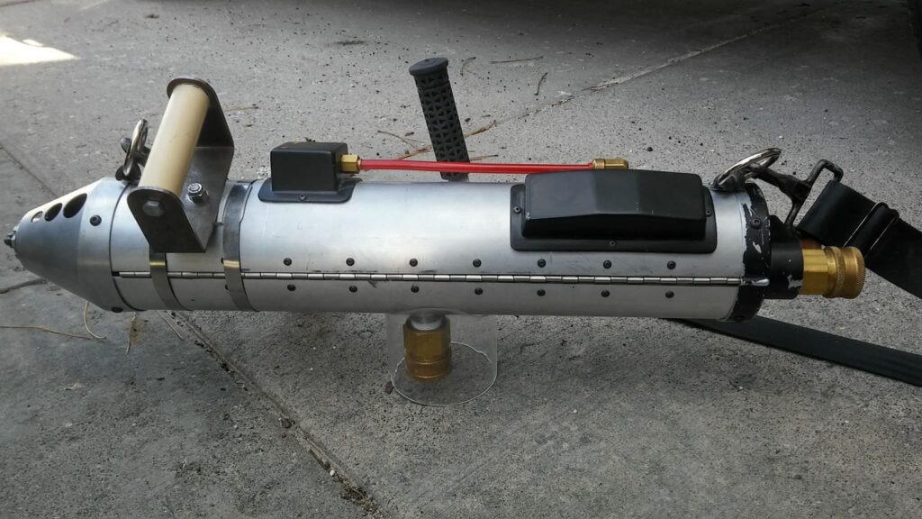
I replaced the awful U-handle base plate I had made a couple years ago. I bought a 3/16″ wall pipe with an inner diameter matching the outer diameter of the blower gun. I had the shop I bought it from cut it down to a 3″ length.

Unfortunately, my phone died after I marked my cut off. I cut out a 2″ section on the bandsaw and then slowly ground down the 1/16″ recessed parts on a belt sander/disc sander, checking the depth of the recess with calipers as I went. It was slow-going, but I like how it turned out.
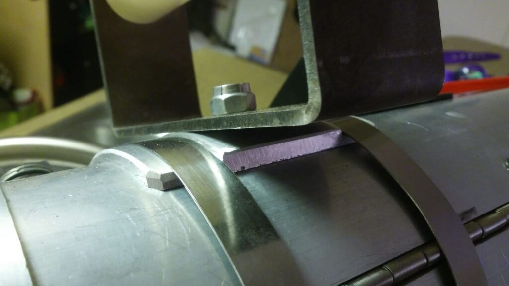
I wanted to wear the blower to a local con, but wanted to fix a couple things on it first. The biggest thing were the heat sinks for it. When I made my blower years ago, I didn’t have many tools. As such I couldn’t cut the bevel into the heat sinks to make them look more accurate. This week I spent a night with the band saw and cut the two extra fins off of each of my heat sinks, cut in the bevel, then mounted them back into the pump boxes with modified L-bar.
Here’s the shot of one of my heat sinks before:

Here’s what the L-bar looks like, which I used to mount the modified heat sinks with:

And here’s where we’re at now:

The last modification to make before Salt Lake FanX was to install some LEDs in the blower’s gun. I’ve been putting this off for a long time. There’s not a lot to say here, other than it really makes the blower gun look neat!
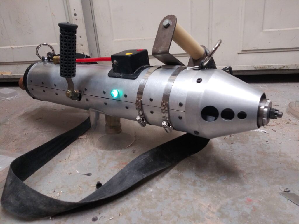
And here’s a couple pics from the con after all the work of getting things updated enough to feel comfortable wearing it:

And that’s as far as I ever got. I had planned to iterate further. I was going to redo most of the pack, as I did with the gun, but I still haven’t gotten to it. Maybe one day I’ll get back to it.
